I have always wanted to recondition the heads in my jubilee even though data does suggest my poor compression is largely down to bore wear. I found two old heads on eBay at a bargain price and thought that reconditioning these would make the rebuild time shorter and also give me some experience in working on these before tackling my originals. I will deal with head removal in a separate post when I get started on the bike. For the time being this is how I stripped the spare heads themselves.
The heads I got were dirty and corroded. One rocker was missing and only one of the three that were present was actually mobile; the rest were solid. There was a lot of dried on hermetite-like sealant on all mating surfaces. Nasty sticky stuff- difficult to remove and it has to come off or little bits can flake off and block something vital! Heads as received are shown below.
This is the left hand head- both tappets present here. The rockers are held in by the bolt and captive nut passing through the head support pillar. This has a cut out in the bolt head that can locate over the flat on the rocker shaft to lock the eccentric in position and thus provide tappet clearance adjustment. Early bikes had a 3 BA sized nut but this was changed later to a 3/16 W/W. and this was also retrofitted when appropriate. This bike had one modified W/W and one BA head.
 |
| LH head- both rockers in position but rusted. Very dirty |
 |
| Loosen 3/16 WW nut |
 |
| Bolt has a special head with a flat facet to lock tappet adjuster |
 |
| Better view of the locking flat |
Once the bolt is out the rockers should simply slip out too. Unfortunately mine were rusted in place. A blow torch loosened the rockers in the head pillars but couldn't unstick the spindles inside the rockers. I had no choice but to use a drift and tap the spindles through the rocker body. I was as gentle as I could be and hoped I didnt bend the mounting lugs.
 |
| Tapping on the rocker spindle to loosen it |
 |
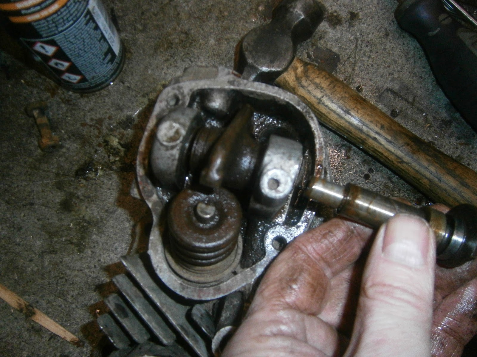
| Rocker spindle could then be withdrawn |
 |
| Removing the shaft leaves the rocker in place. Note there is a spiral spring on one side of the rocker and a thrust washer on the other. Tension in the spring holds the rocker in position after the shaft has been pulled out. In this pic the spring is to the left towards the centre of the bike (ie flat side of head)and the thrust washer on the right |
The rocker shaft then lifts out but take care to note the positions of the spring and thrust washer which are fitted on opposite sides.
 |
| When the rocker is inverted (ie looking down on the pushrod ball), if the ball is held downwards the the spring is on the left and the thrust washer on the right |
I removed both rockers

...and used a small valve compressor to remove the valves. In my case the split collets were stuck/corroded in position between the valve stem and spring head whilst the springs themselves were corroded onto the spring head piece. Nothing could move! This means that any use of the compressor is effectively trying to compress the valve stem... which obviously doesn't compress. This will just bend the compressor so if you think this applies, loosen the spring head piece and collets using a mallet. Flood the collets with penetrating oil and then position a socket over the end of the valve stem so it rests on the spring head piece (not the valve) and give a sharp tap downwards several times to compress the spring momentarily. This can actually remove the collets so it might be wise to cover with a cloth in case they both come out and get catapulted into inaccessible places. I was just trying to loosen everything up so I didn't bother. Eventually the collets shook free and I could use the compressor

The valve compressor worked well but you have to approach from the flat side of the head.
 |
| Withdrawing the double spring and top cap- dirty spring seat left in position |
 |
| Spring components removed and separated- split collets Top left, Spring top, both springs and spring seat but... |
 |
| There is a washer beneath the spring seat which I had forgotten but this just lifts off once the seat has been removed. |
I cleaned up all the components in a sonicator and using a soft brass wire wheel.
Check that the oil way in the spindle is clear- I used a guitar string to poke it through.
Check also these two holes on the top of the rocker itself. There is a groove here to catch oil and drip it through the passages at each end so check that both holes are clear. I found one blocked completely.
I loosely assembled the shaft with assembly lube to prevent new rust before assembly.
The combustion chamber cleaned up well using a Dremmel and a fine brass wheel. This also let me clean the ports. The valves were also cleaned on a soft brass wheel- and in both cases avoiding the stems and the seat. Valves now slipped easily back into the guides. There was a little wear detectable although this was taken up entirely when assembly lube was present so they may be fine in use. I removed any clagged on carbon around the base of the on the inside of the port by careful scraping- there was a lot more there than it looked and it all needs to come out or it will damage the head as the guides are driven out.
The head is now ready for rebuild but I'm not sure whether to replace the valves and guides in this one- there wasn't a lot of wear on the valve stems (third place decimal) and although there was play detectable in the guides it wasn't wildly excessive. I will think about that- no point in reconditioning this head if I discover that my originals are better when they are removed. I already have new valves, guides and springs but I only need to do this job once! As a minimum I need at least to recut the seats and regrind the valves. This will take a little thought as these valve stems and guide IDs are smaller at 7mm than the triumph and BSA guides (8mm) that I'm used to.
 |
| Cleaned combustion chamber |
 |
| Clean head! |
I have got new valves and guides although I may not necessarily fit them to this head. However if not to these two, then I will be fitting them into the heads that I will eventually remove from the bike so I need to be set up to do this.This does present problems:
Firstly, I do not have ether a drift for guide removal or a tool for guide insertion to suit a 7mm valve stem. BSA/Triumph guides have an 8mm stem and so all my existing tools are too large. Secondly I don't have a pilot for my valve seat cutter that will fit inside a newly fitted guide of this size so I cant as yet recentralise the seats.
I made a drift from 9mm silver steel rod by turning down an inch or two to 7mm. It will need heat treatment (which currently I'm not set up to do). I also made a valve seat pilot from a short length of 8mm rod by threading the top for 5/16 UNF 24tpi to match my existing cutter handle and turning the rest down to 7mm giving a comfortable sliding fit through a new guide. Finally I made up a tool for valve guide insertion modelled on the commercial tool I had bought for my BSA.
 |
Home-made valve guide insertion tool
|
This consists of an 18cm length of 7mm mild steel rod, turned down and threaded M6 for 25mm at one end and M7 for 80mm at the other. The rod itself is a nice sliding fit inside the new guides.
The head end piece was made from a 20mm length of 40mm rod turned down to an 18mm face on one end by a 45degree taper and centre-drilled tapped to M6. The taper should self-centre in the valve seat before the new guide is drawn in. The rod above threads right through this head and can be secured with an M6 locknut so that it can be held during guide insertion.
The slider is made from 15mm brass rod faced and bored to 7mm to slide easily along the main rod and I made a compression nut using a 20mm length of 15mm hex rod centre-drilled and tapped to M7. The brass slider is flat-faced as the new guides have an obvious flat facet on their backs and brass shouldn't damage them. The hex rod was used instead of an M7 nut to give a longer thread engagement in order to spread the load. Its not that I think enormous forces are needed to insert a guide- its more that my threads aren't very good quality! This tool does (should!) allow guide insertion in a cold head but I will not risk that and will preheat the head to 100 deg in my boiling bath anyway. Similarly I will be chilling the guides in the freezer to assist the fit.
 |
| tapered head, self-centreing |
The head is reusable and can be applied to guides of any- other peculiar ids if required by making up an appropriate M6 threaded guide rod, slider and nut.