Anyone know how to put this wheel back together? I am puzzled by
1. Where can I get a new hub oil seal? Diagrams show felt seals but the bike had a thin rubber seal here... I can get a suitable width and hole size but only too thick. Has anyone found a more suitable seal?
2. Secondly, the order and arrangement of the spacers etc on the front axle is confusing and I cant find a the best way to assemble. Sadly I'm not absolutely sure how it goes back ... Or if it was put together right when I got it, but all orientations seem to give some sort of problem, floating forks etc.
If anyone has a bike with this pattern of front wheel please let me know how its assembled.
Thanks
....Well my previous post about the front wheel turns out to have been premature and I still have problems fitting it. I have made many enquiries and eventually turned up these two diagrams for front wheel mountings ... Although there are probably more than two such versions. The early bikes had an arrangement where sleeve nuts fitted on both ends of the spindle, removing these allowed the spindle to drop out vertically through slots in the bottom of the forks. My earlier bike has this arrangement and it features a spacer and a second nut inboard of the left hand fork which presumably retains the hub as an intact assembly as its slipped down and out of the fork (nos 20 and 21 below). The oil seals in this wheel are felt washers both sides each retained by a two part enclosure the outer part of which appears to be quite large (14 in plate E). The rhs spacer inside the hub (ie the one that fits into the RHS oil seal, 13 in plate E) is separate from the hub nut/bolt, the LHS spacer fits into the oil seal on the LHS.

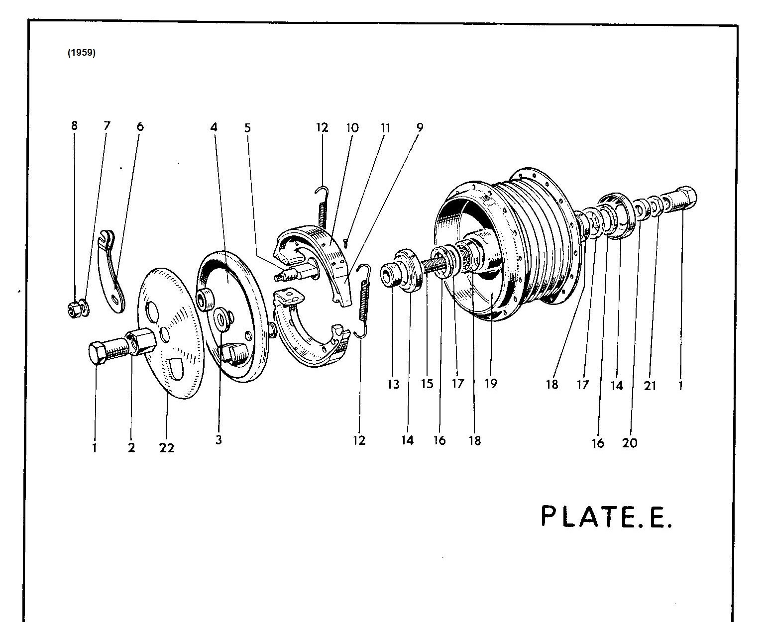
One for 59 and one for later shown in the 1963 re-issued parts list with drawings. This is shown below:


There are several differences although the main one is that the spindle has been changed removing the need for the sleeve nut on the RHS, this is replaced with a cast hole allowing the spindle to be held securely whilst the sleeve nut on the LHS is tightened or loosened. The internal hub spacer on the RHS has now been amalgamated into a modified hub fastener (3) which penetrates the felt oil seal when the hub is assembled. This oil seal is now containied in a slimmed down enclosure (17 plate EB) that's a neat fit inside the hub core (rather than over it as in the earlier design... I think). The Left hand side has also been modified. The oil seal has been replaced with a rubber seal (18) retained in a one-piece slim enclosure identical to that now on the RHS (17), and the 15mm spacer and second (hub retaining) nut have vanished, although now the larger cover (14 in plate E) that presumably used to be used as the "enclosure" for the felt washer is now referred to as a "spacer" itself (16 in plate EB) and has presumably been modified from the simple cover present on both sides of the '59 wheel (14 in plate E) to combine the functions of both cover and spacer in a single part. Certainly these two parts have different part numbers but the diagram is insufficiently clear to explain any difference between these components.
This change is listed in terms of parts in the 1961 parts list supplement, although this has no diagrams. The change in design took place between the two bikes I own and the question is whether it was introduced in one go or via a transitional stage. The reason I raise this is because my wheel is the later type from the RHS, through the bearings and hub (and even had a LHS rubber oil seal when dismantled) but beyond the oil seal my spindle still had a cover and a separate 15mm spacer, looking quite like the earlier bike setup- although the LHS internal thin hub nut in the earlier design is not present. So... was this a transitional fitting where perhaps the spacer and cover were left separate for a time, a later mod by a PO, or is the diagram wrong in that the possibility of a separate spacer has simply been missed out of the 1963 illustration and list?
The whole thing is compounded because I cant get the wheel to centralise in a fixed position. This is because unlike other bikes where a nut bolts up against the fork leg to tighten, the sleeve nut tightens through the fork leg, the leg itself can slide along the sleeve no matter how tight the bolt is fastened- unless something such as a spacer holds the leg in one position on the sleeve and prevents this movement. Presumably all play should be taken up when the sleeve nut is tightened, meaning that the head of the nut should be flat on the outside of the fork, the spacers should be nipped up through the oil seal and against the bearing. There should be no free sleeve nut visible either inside or outside the fork as this would allow the fork to move along the sleeve so I assume that this must slip inside the spacer as its tightened through the fork leg. In my case when the sleeve nut is tight there is still movement in both the spacer and fork leg... which in turn means the wheel isn't held firmly in its central location. I cant help feeling that the problem lies in the spacer on the lhs which is too short... or perhaps the modified spacer/enclosure that should be here has been broken or missing and replaced with parts from a 59 bike?
 |
| Not always quite so lonely in the garage- here an occasional visitor! |
 |
| Front wheel spindle as removed. Note all fixtures on the right have been reassembled into the brake plate and hub assembly. The solid axle terminus is on the right in this photo and the sleeve nut and spacer on the left. Note that the spindle has slight shoulders machined into it and also that the spacer has one chamfered and one square end. When removed the chamfered end was towards the outside of the spindle on the LHS. |
 |
| Interestingly the spacer sits in different positions; when fitted each way round. Chamfer inwards it slides onto the axle over the machined shoulder to the position marked in blue... |
 |
| ... and chamfer outwards (as it was found on removal) it slips on only to the position shown above. |