1. Footpegs are loose on their fittings- they are a strange fitting that is neither taper nor spline, its a sort of multifaceted stud that fits into a hole in the peg with similar profile. The trouble is any wear in the facets allows the peg to move slightly fore and aft (in the bike's direction) and this play can't be eliminated by tightening the nuts. It needs some form of packing to tighten up the fit or perhaps some weld to build up the low spots again coupled with refiling to restore the profile... but this seems a tricky job. I will probably see if I can find anything to pack the joint, metal exhaust tape perhaps?
2. The exhaust header pipe seemed a little loose in the head. This can be fixed (surprisingly ) using bathroom silicone sealant ... I am told- and I'm assured that it doesn't burn. However in the same vein I found a Copper-containing high temp silicone gasket maker from V-tech- just made for these applications!

The exhaust went in easily and sealed perfectly.
OK... moment of truth. The PO had started the bike for me when I collected it- it started reluctantly but it did start. It didn't run for long though but I was satisfied that at least everything was place- and I was buying it as a bike-with-a-problem anyway. He had also pointed out that it was smokey- at least on starting.
Well after a good tickle the bike started gratifyingly on first kick- however it wouldn't run-on. I found that the air slide had to be fully in to get running at all and the throttle needed constant blipping to keep it running. There was also the occasional spitting back through the carb. What was worse- as the running went on the motor got smokier and smokier. I also found that the kick start began to "slip" and cycled without compression- I'm not sure why but currently I favour clutch slip. The clutch centre turns and the rear wheel does turn when the bike is in gear even when these slippage events occur which suggests that the clutch outer is also turning... but I cant confirm this or tell if the motor is turning without compression or just not turning...? Need to check but unfortunately I cant kick it and make the observations at the same time so a bit of help would be useful. Perhaps the primary chain case is overfilled?- Try the simple solutions first!
Well I had always suspected that the valves and/or guides needed attention, I suspect the increase in smoke is telling me the same thing as the oil gets pumped up to the rockers in greater quantity as the new stuff works its way around the system. I checked oil return and it was flowing very nicely into the oil tank. One slight problem though- my bike has no dipstick and oil level isn't visible so it might even be a little over-filled which would also perhaps contribute to the smoke?
The requirement for full choke was at odds though, burning oil should richen the mixture and then full choke could lead to smoking from poorly burnt petrol as well! However spitting back is usually an indication of weakness- so even full choke is apparently too weak??? This requirement for full choke and the failure to run on I have seen before. I had virtually the same symptoms on my Triumph TR6 650 and then it was a classic blocked pilot jet in the carb. Although I do not think by any means that this is the Jubilee's only problem, a carb strip down and clean seems like a good idea so that was the next step. Sadly my camera charge expired soon after starting so some of these pictures are mock-ups taken after the fact.
Removing the Carburettor
Removing the carb should have been easy... just undo the top retaining ring and lift off the top complete with throttle slide and choke still attached to their cables. Then undo the two nuts on the carb body mounting flange, and slip the rest of the carb back from the motor and off the studs...
Well that was the theory!! Unfortunately Norton have thought of that and carefully manufactured the bike so that the clearances are just too small! The backward clearance behind the carb is just less than the amount required for the flange to clear the studs, whilst the top clearance is just inadequate to remove the carb top and slides! These are only a little bit smaller than required but enough to turn a simple process into a swearing nightmare! Well removing the tank isn't a big deal but its a step that shouldn't be necessary- anyway top clearance solved. Rear clearance- well the frame cladding is in the way and removing that would be a real bother for a quick job so I managed eventually to finagle the carb off and out around the studs with a little swearing and relatively little collateral damage to the frame cover- I'm going to repaint eventually anyway! I think if I can shorten these two studs by about 3mm each I shouldn't have this problem again. (later investigation showed this isn't possible unless the nuts are thinned as well and this could result in insufficient thread to hold the flange)
 |
| the offending studs |
 |
| Carb top, cables and sliders removed. |
Carburettor strip:
In my book carburation is a black art; After many years thinking about them I have a sort-of understanding of what's what- but as each carb differs, I always have to work it out again from first principles. There will be a large element of "sucking eggs" for the more experienced reader- but its the process I go through to work out whats what and how it should be put together... So Apologies, feel free to skip!!
 |
| Carb as removed; Parts from the bottom- main jet retaining cover and nut, Pilot jet cover (right),Throttle stop screw (centre); carb body or jet block retaining screw (small black), Pilot air screw (far right) |
 |
| Carb as removed. Parts from bottom: Main jet cover nut (base), main jet holder nut (larger immediately below float chamber), three float chamber cover retaining screws, tickler (centre), banjo fuel inlet (right) |
To help with their carbs, Amal made (maybe still make?) this handy spanner. It fits pretty much all of their nuts although you cant use it on all of them because of geometrical constraints on access. Still if you have this (few quid on eBay) and a 1/8 and 5/16 WW spanner you should be fine! However having said that my carb had an aluminium bell mouth fitted. I simply couldn't unscrew that as it was locked onto its threads and there isn't anything firm or graspable to grab and turn. I left it for later when it did in fact come off after cleaning.

The first job was to unscrew the banjo-retaining nut and lift off the fuel inlet and filter beneath. Obviously this should be clean but finding muck here boded well for my blocked pilot jet theory!
 |
| Removing the banjo union- fule filter beneath. Fuel arrives around the external periphery of this filter and is strained as it passes centrally and down into the carb. Muck here traqpped by filter clearly visible |
Unscrew the three float camber cover screws and lift off the float chamber cover. This had been sealed with what I think is red Hermetite--- I haven't seen that stuff in ages! Anyway this had made the screws quite stiff where it had got down into the threads so a good clean was necessary. This gasket sealer can also get detached and could also block up a jet or two... so also good for my theory I think!
 |
| Screws out- hermetite in threads visible. Bell mouth resolutely still attached! |
 |
| Brass bush removed- note base of needle valve behind. Note hermetite |
 |
| needle in position |
 |
| float lifts out |
Once the cover is off remove the float and the small brass spacer on top. I don't think its possible to refit the float backwards but the spacer could be wrong so note that its on top of the float when the cover is removed. Remove the float and shake it to see if there's any liquid inside- this one was dry! If the float is leaking then it can be re-soldered, but its probably as easy to replace it with an ethanol-safe stay-up version from Burlen.
 |
| Old style plastic needle |
Having removed the float, pick out the needle from the inlet needle valve seat in the top of the chamber. This one is the original all-plastic needle; these can fail over time so there is now a viton-tipped needle available that's thought to be better- I will definitely replace this part. Check the bottom of the chamber for sediment-this leads directly from the bottom of the chamber to the main jet so muck here has good access to the narrow spaces in the carb and jets. I found a small amount of very fine sediment here.
 |
| Sediment in bottom of float chamber, note red Hermetite that needs cleaning off before refitting the cover. |
Remove the main jet assembly. I unscrewed the larger of the two base nuts which retains the whole jet assembly in the carb. This came off with its washer and could then be disassembled by gripping the base nut in a vice and screwing the main jet holder out of the body with the spanner.
 |
| unscrewing jet assembly via large nut |
 |
| jet assembly removed |
 |
| hold base (cover) nut in vice and unscrew jet holder body |
 |
| Unscrew needle jet from top of holder- main jet from base. |
Once the main jet holder is out then the main jet can be unscrewed from the base and the needle jet from the top. Check everything for blockage. I have found some shockers- but not in this case, all the jets and holes in the jet holder were nice and clear. There was a small amount of crud in the lower threads of the main jet holder, and some inside the main jet cover nut but I doubt that this had been causing a problem.
 |
| Inside jet holder, crud in threads. |
The next step is to remove the pilot jet cover and its washer -you will need to 1/8WW spanner for that. The cover comes off to reveal the pilot jet itself which simply unscrews.
 |
| 1/8 w to remove pilot jet cover. The jet underneath just screws out. |
I next removed the two spring-loaded screws, the throttle stop (larger) and the pilot air control screw. I usually screw these in fully counting the turns before I then remove them completely so I have a guide to returning them to their approximate positions.
 |
| Remove spring loaded screws having noted their position, also remove jet block retaining screw |
Next I removed the jet block screw completely and it was then possible to remove the jet block. According to the protocols, this should simply ease out with finger pressure- no such luck. I had to invert the carb and gently tap the block out with a soft metal (aluminium) drift. The block came free with its base washer present (this is really important; I had hoped that it might be missing to give a nice explanation!). The jet block showed signs of blackening through backfire, but its drillings were clear.
 |
| "Ease" jet block out... finger pressure? |
I didn't want to remove the tickler or needle valve seat as I couldn't see any problem with either of those so this was about the limit of my dismantling. The next step was to clean everything thoroughly. At this stage I cleaned using an aerosol of carb cleaner with the extension pipe to get into all the openings. I couldn't really say that I found anything to give great concern, yes I had found a little sediment here and there but no jets were blocked and all the holes seemed clear. Its also necessary to clean out the drillings in the carb body. This is a little more tricky. You can use the carb cleaner and you will get an obvious blast of spray emerging from any openings that any particular drilling communicates with. The problem is that its not always apparent how many openings should communicate with any given passage- and if one is completely blocked you might therefore miss it. Sometimes you can get an idea of where they go by looking at the carb body, the course of an internal passage in the body can often be traced by following the tubular bulge in the casting onward from any particular opening. I am particularly interested in the pilot jet which should communicate to several other drillings and to understand how many and where to find them I needed to know a bit more about how the pilot system works. There is great account of how the carb works on the Hitchcock's site but its heavy going. Try clicking on :
http://www.hitchcocksmotorcycles.com/hints-tips-monobloc and then select "How it works and part names". I have taken the following diagram from that site and added my own explanation which I hope will be a little clearer- although possibly not entirely right!
Operation of Pilot Jet
1. Fuel flows up a 45 degree channel (10) from the float chamber fuel pool which flows through and surrounds the main jet assembly. The channel opens just above the base of the jet block to reach the base of the pilot jet (9). As this is below the fuel height in the float chamber there should always be a pool of petrol here.
2. Even when the throttle is closed, air can still enter the carb body via the primary air channel (35) which opens through one of two holes just below the main air intake on the back of the carb. This channel communicates with the space surrounding the needle inside the jet block. From here it can pass through the horizontal channel (31) in the jet block just above the needle jet, past the pilot air adjusting screw (not shown in this diagram) which regulates the flow, to communicate with the top of the pilot jet. This means that air can always reach to top of the pilot jet and fuel can always reach the bottom. However unless there is anywhere for the air to emerge this wouldn't achieve anything.
To allow the air/fuel mix to emerge into the carburettor throat (and thence to the motor) there are two small holes drilled from the carb throat that communicate with the primary air channel (pilot air system passages). The first is the Pilot jet main outlet (7) situated directly above the pilot jet, and the second is termed the pilot jet bypass (8) and is positioned in the jet block under the throttle slide.
The system works as the motor turns and sucks on the carb, pulling in air. If the throttle is closed then air can't enter easily through the throat as this path is blocked by the lowered throttle slide (5), and so this suction acts mainly on the two drillings inside the carb throat. As the throttle is closed the second opening (8, the bypass) is relatively shielded by the throttle slide itself, so the whole suction effect of the descending piston acts to pull air out of the pilot jet outlet. This pulls air into the carb through the primary air channel, forcing it to flow along that channel, past the adjusting screw and over and around the top of the pilot jet, and then up, out of the carb body and into the throat through the main pilot outlet (7). As this air is sucked over and around the pilot jet, the fuel is also sucked, through the jet, atomised by the holes and openings in the jet and mixed with the air. It is this fuel air mixture that emerges through the main pilot jet outlet into the carb throat downstream of the throttle slide. From here it can flow onwards to burn in the motor even when the throttle is fully closed. As the throttle is opened, more air is drawn into the motor past the throttle slide itself meaning that the suction experienced at the pilot outlet hole (7) is decreased. However, the throttle slide cant take over and supply all the air/fuel required all at once, so there is a second drilling (8, pilot jet bypass) situated directly under the throttle slide (and actually part of the jet block), that adds fuel/air via the pilot system at low throttle openings before the slide moves up far enough to supply the motor entirely by itself.

1. Mixing Chamber 2. Mixing Chamber cap
3. Carburetter Body
4. Jet Needle Clip
5. Throttle Valve
6. Jet Needle
7. Pilot Outlet
8. Pilot by-pass
9. Pilot Jet
10. Petrol feed to pilot jet
11. Pilot Jet Cover Nut
12. Main Jet Cover
13. Main Jet
14. Jet Holder
15. Needle Jet
16. Jet Block
17. Air Valve
18. Mixing Chamber Cap Spring
19. Cable Adjuster (Air)
20. Cable Adjuster (Throttle)
21. Tickler
22. Banjo Bolt
23. Banjo
24. Filter Gauze
25. Needle Seating
26. Needle
27. Float
28. Side Cover Screws
29. Pilot Air Adjusting Screw
30. Throttle Adjusting Screw
31. Air to Pilot Jet
32. Feed Holes in Pilot Jet
33. Bleed Holes in Needle Jet
34. Primary Air Choke
35. Primary Air Passage
36. Throttle valve Cutaway
The upshot of this is that for correct pilot jet function, squirting carb cleaner into the hole from which the pilot jet has been removed should show 4 outlets; it should flow downwards and out of the fuel inlet drilling, inwards to emerge from the air intake hole and upwards to emerge out of both outlet and bypass holes (note if the jet block has been removed, it will just squirt horizontally out of the air passage into the throttle chamber). In my case I could see it emerge from the fuel and air intakes and from the main pilot jet outlet, and into the throttle space as above since I had removed the jet block which contains the 90 degree bend and bypass drilling... well I wasn't looking for that at the time! However nothing seemed to be blocked so no explanation here. Of course it is necessary for the openings in the jet block to align with those in the carb body or airflow will be interrupted and given the tightness of this block then perhaps it was jammed in, and out of alignment? I will need to check this and the remaining pilot bypass drilling when I get back into the workshop.
In the meantime I put all the components into a sonicating bath to clean at 65 degrees. I know this doesn't work very well as I have only a low power sonication bath more suited to jewellery than engineering (!) but hopefully it will loosen up anything I couldn't clear by blasting through with carb cleaner. I should then be able to flush the system out with the water/detergent mix in the cleaner and a dropper pipette. Incidentally if you do find a blocked passage or jet the advice is to clean it with a blast of air... good luck with that! When this stuff crystallizes in the carb its quite granular and pretty hard. You can buy a set of carb cleaning wires but frankly I think the high "E" string from a guitar is pretty much perfect... its smaller than most jets and a single poke will shift virtually anything- its also flexible enough to get around many of the drillings in the carb body. However, don't scrub or rotate it as this will definitely enlarge the jets!
So-- back in the workshop... After a good clean and dry- I did find something that might be interpreted as muck in both the pilot jet and the bypass hole, although neither were by any means actually blocked. Then its reassembly time. To be honest I don't think I found nearly enough dirt in the carb to account for the running behaviour but I won't know until I test it. For reassembly I bought the 375 gasket set from NOC. Its cheaper than the set from Burlen but I wouldn't get it again. Although the fibre washers are fine, the gaskets and paper washers didn't fit well. It was hard to get the jet block base washer on without tearing and the screw holes didn't line up properly in the float chamber gasket. The gasket tore when I tired to enlarge them and I had to cut a new one out of some nitrile rubber sheet which fits much better. I cleaned the threads of the three cover screws by chasing with a 2BA die nut.
I fitted new fibre washers under the main jet assembly, pilot jet cover nut and banjo bolt- and a new paper washer under the jet block. The block was checked carefully to make sure that the pilot jet bypass (which exits through the block) was clear, and that the air passage holes in the block lined up with those in the carb body by poking the plastic tube from the carb cleaner can through to check for access. Having ensured it was fully seated I refitted the retaining screw. The banjo filter on my carb had the integrated flange and so doesn't need the bottom washer seen in earlier versions.
I refitted the air and throttle stop screws having cleaned their threads. (Screw fully "in" and then "out" 1.5 turns as a good starting point if you have no data from their original positions).
The NOC kit doesn't include a new "O" ring for the intake flange; although mine seems in good condition I would prefer to change it as this can be a cause of a weak mixture and the spitting back I had noticed before. I will see whether any I have will fit although most of mine are metric and this will be an imperial size... Note added later- a R23 O ring fitted perfectly!
Finally, I detached the intake trumpet which was loosened by sonication and cleaned its threads. I will apply copper grease here to prevent it seizing again when I reassemble, but I wont refit until the carb is on to try and get a little more clearance for refitting.
Carb refitted... you can get more clearance if you remove the banjo housing and filter, its then just possible to wiggle the carb in. My frame covers have been pop-riveted into place so I am suspicious that the covers on this bike aren't original... they have a suspicious look of the "home made" about them! Unfortunately I have no comparison as they are missing from the red bike but I'll try to find some pictures online.
Given the possibility of muck in the carb from last time I fitted an additional in-line fuel filter to make doubly sure that this can't happen again.
Well dear reader- you have probably guessed that the work above has made not a jot of difference to the bike's running... in fact if anything it runs less well now than it did but at I am now certain that the problem isn't the carburation.
I was able to show that the pistons were still moving up, even when the engine seemed to have lost so much compression it felt like clutch slip! There was also a nasty black deposit on top of the pistons and nasty black stuff on the plugs. Finally I did a compression test- dry I got 40 and 70 psi, and wet both shot up to over 140 psi!! The initial figures are so low this does suggest that there is something horribly amiss inside this motor and the increase on adding oil suggests that this is largely bore/piston wear. A full strip is now essential and almost certainly a rebore or barrel swap as well as the top end overhaul I had anticipated.
So-- back in the workshop... After a good clean and dry- I did find something that might be interpreted as muck in both the pilot jet and the bypass hole, although neither were by any means actually blocked. Then its reassembly time. To be honest I don't think I found nearly enough dirt in the carb to account for the running behaviour but I won't know until I test it. For reassembly I bought the 375 gasket set from NOC. Its cheaper than the set from Burlen but I wouldn't get it again. Although the fibre washers are fine, the gaskets and paper washers didn't fit well. It was hard to get the jet block base washer on without tearing and the screw holes didn't line up properly in the float chamber gasket. The gasket tore when I tired to enlarge them and I had to cut a new one out of some nitrile rubber sheet which fits much better. I cleaned the threads of the three cover screws by chasing with a 2BA die nut.
 |
| Cleaned parts ready for reassembly |
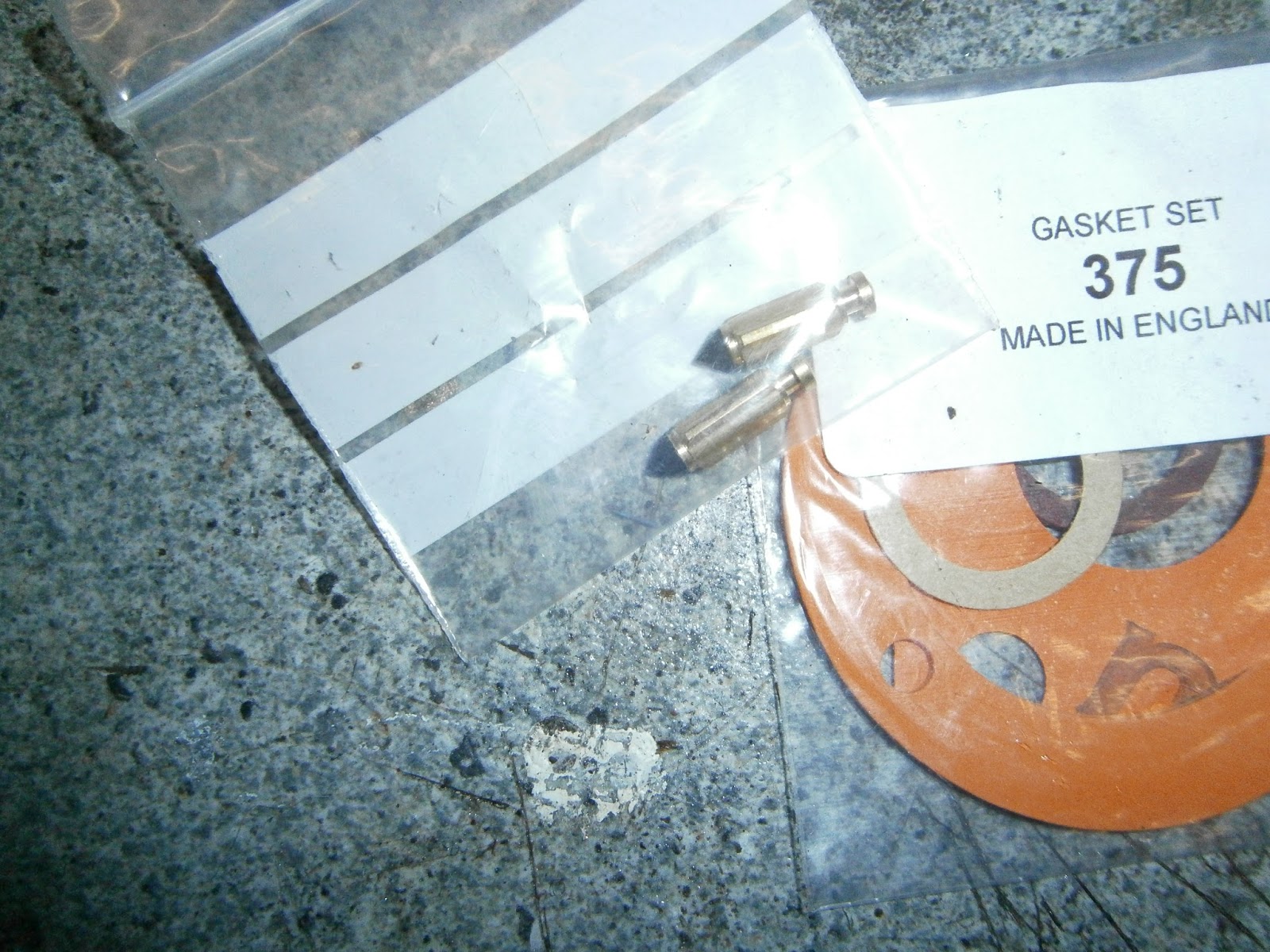 |
| NOC gasket kit 375 plus new needle valves |
 |
| New paper gasket on base of jet block |
 |
| Jet block installed- checked alignment of air intake holes to air passages in the body |
 |
| Jet block in place (from above) |
 |
| Inserted pilot jet and then pilot jet cover with new fibre washer |
 |
| Inserting control screws- this one the pilot air regulator |
 |
| Needle valves compared- old valve on right is all plastic, new valve has viton tip |
 |
| Needle valve, float and brass bush installed. |
 |
| Main jet assembly rebuilt and new fibre washer |
 |
| New fibre washer under banjo union nut, black nitrile gasket to float chamber lid. |
I fitted new fibre washers under the main jet assembly, pilot jet cover nut and banjo bolt- and a new paper washer under the jet block. The block was checked carefully to make sure that the pilot jet bypass (which exits through the block) was clear, and that the air passage holes in the block lined up with those in the carb body by poking the plastic tube from the carb cleaner can through to check for access. Having ensured it was fully seated I refitted the retaining screw. The banjo filter on my carb had the integrated flange and so doesn't need the bottom washer seen in earlier versions.
I refitted the air and throttle stop screws having cleaned their threads. (Screw fully "in" and then "out" 1.5 turns as a good starting point if you have no data from their original positions).
The NOC kit doesn't include a new "O" ring for the intake flange; although mine seems in good condition I would prefer to change it as this can be a cause of a weak mixture and the spitting back I had noticed before. I will see whether any I have will fit although most of mine are metric and this will be an imperial size... Note added later- a R23 O ring fitted perfectly!
Finally, I detached the intake trumpet which was loosened by sonication and cleaned its threads. I will apply copper grease here to prevent it seizing again when I reassemble, but I wont refit until the carb is on to try and get a little more clearance for refitting.
Carb refitted... you can get more clearance if you remove the banjo housing and filter, its then just possible to wiggle the carb in. My frame covers have been pop-riveted into place so I am suspicious that the covers on this bike aren't original... they have a suspicious look of the "home made" about them! Unfortunately I have no comparison as they are missing from the red bike but I'll try to find some pictures online.
Given the possibility of muck in the carb from last time I fitted an additional in-line fuel filter to make doubly sure that this can't happen again.
Well dear reader- you have probably guessed that the work above has made not a jot of difference to the bike's running... in fact if anything it runs less well now than it did but at I am now certain that the problem isn't the carburation.
I was able to show that the pistons were still moving up, even when the engine seemed to have lost so much compression it felt like clutch slip! There was also a nasty black deposit on top of the pistons and nasty black stuff on the plugs. Finally I did a compression test- dry I got 40 and 70 psi, and wet both shot up to over 140 psi!! The initial figures are so low this does suggest that there is something horribly amiss inside this motor and the increase on adding oil suggests that this is largely bore/piston wear. A full strip is now essential and almost certainly a rebore or barrel swap as well as the top end overhaul I had anticipated.