This part of the blog is mainly a record for me to use in the rebuild- but it also includes a bit about the wiring I found and what I did to sort some of the problems.. of which there were many, but mainly just untidy and insecure joints. The wiring in the bike has clearly been greatly mucked about with and several parts of the nacelle/headlight mount were missing, its possible that the whole loom has been changed for a pattern type with different wire colours but as its inconsistent, I think its more likely to have just been modified "like Topsy".. Anyway-here we have it...
 |
| Headlamp held on with tape, rim loose on glass unit. |
 |
| Reason for the tape: No lamp fixing clamp |
 |
| Bulb connection doesn't fasten to rear of lam, it just falls off |
I managed to bend the securing tabs on the bulb connector and this enabled it to grip the rear of the light unit securely. I also ordered some Lucas wire bulb clips LU500291. These simply clip to the chrome rim and clamp the light unit and rim together. Very simple fix but very satisfying!
 |
| Bulb holder and wire clips installed- much better! |
In order to continue with the fork strip I had to remove the second fork top cover which means that the nacelle will need to be disconnected. I will take this opportunity to install a grommet to the bottom cable entry. Firstly I removed the speedo cable. Its then necessary to disconnect all wires that pass into the nacelle- starting with the 3 wires that serve the headlight connector
 |
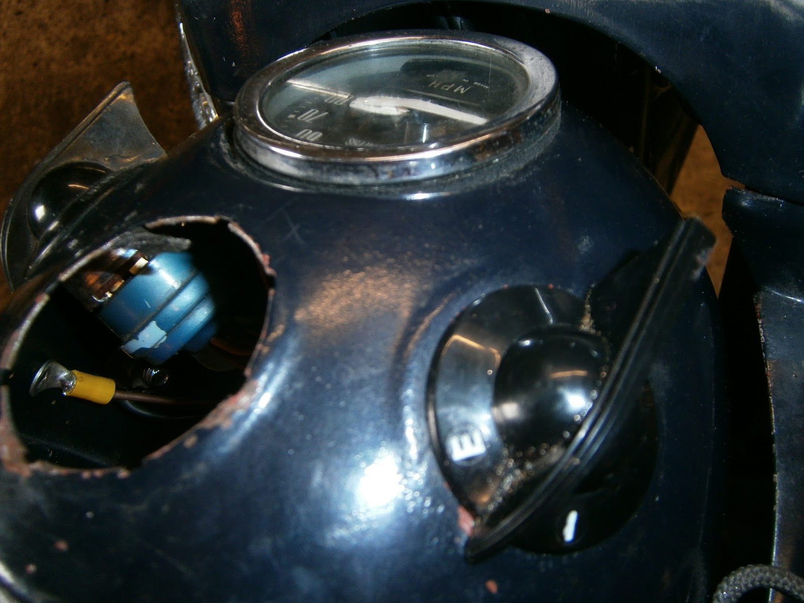
Headlight unit- three wires 2 red (new- should be brown) and a new green/blue earth going to 2 black and yellow- the yellow wire is really "translucent" in Norton parlance but has oxidised and yellowed. Translucent generally used for Earth wires. On this bike much had been replaced with red from the battery and under the saddle- not a bad choice for a positive earth bike, but here in the nacelle red has been used for the power feeds to the headlamps- and the green/blue is the earth... now does that sound to you that its likely to lead to confusion at all... ?
|
 |
| Switch connection- removed at right nut- brown and black wires, ring connector.- choc box domestic wiring connector to be removed. Note ammeter held in by a jubilee clip around the base... Not sure how it should be held as this type of meter has only two posts- both terminals! The clip mounting posts are absent so it was likely to have always been a push fit. This one is siliconed in around the bezel as well. |
 |
| Double bullet connector, brown/black to brown |
u
 |
Single bullet brown to clear- this wire was thinner than usual and the bullet didn't fit; it pulled off rather than coming out of the connector. The wire will need to be replaced later once I have worked out where this new wire actually goes, For the time being I have crimped a new bullet made for thinner cable. This was reconnected and the contact broken at the lower point as shown below.
|
 |
| Bullet connector- black to black and clear (thin wire with new bullet) to brown, I'm sure these wires should be changing in gauge |
 |
Non std Lucar connector pulled off instead of disconnecting.. I replaced it with a red insulated crimp terminals (bullet style) making a green to green wire connection. Note the wire-weaving macrame of non-std red wires at the rear!
|
 |
| New grommet installed. |
 |
| New headlight clamp installed at bottom of nacelle. Green black and green blue wires never used by Norton. |
Reassembly
Well a bit of a nightmare but in the end it all went back together quite easily. I like wiring to be neat, but here its clearly a lost cause! The photo records weren't perfect but very useful nonetheless. I found that there were quite a few taped connections under the saddle where the loom had been greatly abused in the past- and a lot of non-standard wire installed. I spent an enjoyable couple of hours re-soldering those joints that were meant to be permanent (covering them in heat shrink
NOT insulating tape which leads over time to a disgusting sticky goo!) and fitting new bullets to those connections that should be detachable. Owing to the abuse this poor loom has suffered in the past there didn't seem to be much point in trying to keep it standard so I just used modern coloured crimped terminals rather than the correct bullet style. They don't look right but should be fine until I strip and replace the loom completely (if I ever do....). There were several places where the loom had either been shortened or was never long enough in the first place! In those I fitted extension wires via soldered joints using the same colour of wire.
I also replaced the rear light assembly (cracked lens and butchered mounts!)
 |
| New backplate in position- a repro sadly but all the originals I have are cracked |

... and ordered a new 6V3W bulb for the speedo light. I did wonder about using the 6V4W sidelight bulb that I already had for this; its a std BA9 fitting so it did fit and work, but the glass part was a bit too high to fit easily into the speedo clip without fouling the nacelle case. Interestingly this light was formerly intended to shine through the two "warning lights" visible in the earlier smaller nacelle. I don't think this told you anything other than the ignition is "on" as the speedo light was on permanently - whenever the ignition was turned on that is... and thus the bulb was subject to frequent blowing... These warning lights were deleted in 1961 when this type of larger nacelle was fitted with a WIPAC 7 inch light.... Strangely I still have a speedo light, its possible this speedo isn't the original- mileage is off anyway, so I will check whether it illuminates all the time or only when the lights are on.
 |
| Speedo clip to receive instrument panel bulb - awkward or what??? Viewed from below the bulb holder clips into this spring clip and just shines through a slot in the side of the speedo- bit primitive. |
Interestingly during my poking around I discovered that the bike has a rectifier but apparently no regulator. Instead there is a resistance wire (coated in heat resistant sheath) that is usually switched in to drop the charging voltage during normal use. It's switched out if the starting switch is set to "Emergency" giving maximum alternator output to the system for starting if the battery is weak... its almost as if they expected this to happen a lot....?
 |
| Rectifier mounted behind carb via one bolt which... |
 |
| ... also serves as the main earth connection for the battery positive terminal on the other side- in this case red wire replaces the stock translucent/colourless earth wire. This seems a strange place as a good backfire could melt the flex?? |
Anyway, this seems to be a primitive system which I would guess isn't very kind to batteries so I will see if there is an upgrade to a modern reg/rect 6V pos earth. I know these are available for the BSA C15 as I have fitted one in the past, but they are expensive and it might be more cost effective to upgrade to 12V if this is possible- must check the forum. I found this excellent article on upgrading these lightweights... I will probably do this when I rebuild/rewire/repaint.
http://www.aoservices.co.uk/info/NORTONLGTWT.pdf
In the meantime I reconnected the resistance wire by soldering it onto the loom- it doesn't take solder well- either because of its composition or condition, but I cleaned it and wound the loom copper wire around it to get a good contact before soldering. Even so this was an awkward connection. I must investigate whether there should be a screw terminal for this connection?
 |
| This was originally an unholy mash of 4 wires embedded in poor solder. I separated these and connected a red lead to the resistance wire covering in heat-shrink. This allows the resistance lead to rejoin the loom wire at a new bullet (2 wires inserted) whilst the other part of the bullet connects to the earth contact at the rear of the rectifier. |
I also contacted the club about the odd square facets to the nacelle mounts and they sent me this diagram of the original Wipac mounting system...
 |
| 1 is a chromed, gently domed headed bolt, 2 is a washer and 3 is a dished washer (hollow underneath) to accommodate the tangs of the nut cage. |
The square cutout in the nacelle is supposed to receive a caged nut (currently believed to be 5/16 BSF). Although bolts and the odd washer are still available from the club, the nuts aren't. I did however discover that something very similar is still supplied for the Morris minor so I ordered a couple from ESM Minor spares (
www.morrisminorspares.co.uk/) - part numbers FIX207 (sq nut) and FIX207C (cage). They seem to be fine except the retaining tangs are too long and will need to be cut down. This nut is also made to be fitted behind the surface with the tangs holding it- the nut isn't held in the cage so I think some more modifications will be needed.
 |
| New cage nut- the tangs will need shortening to just grip the nacelle and the two side walls will need to be nipped in to hold the nut- possibly best to weld it here. |
... Well sadly this didn't prove to be a direct replacement for the original part - partly because its a little bigger but mainly because it lacks the in-built clips that fix the original to the nacelle shell. However it can be used because the thread is a perfect match and with a little effort it can be made to resemble the original fitting. If you don't want to do that just weld the tangs onto the inside of the nacelle and use a blob of weld to retain the nut in the cage.
However I did the following- its crude and could certainly be done more neatly, but this is what I did. The new fitting is a little larger than the original;
although the nut will pass through the square cut-out in the nacelle the cage
will not. This isn’t a bad thing but it means a little modification is needed.
Firstly I reduced the sides of the nut cage by about 2mm
each. In retrospect this may not have been needed but I had expected it to be
required to allow the nut to sit snugly against the nacelle shell.
 |
| Cage held in vice, I cut appx 2 mm off the sides using a disc cutter |
At this stage its an excellent idea to fit the nut and use a
vice to squeeze the newly shortened sides against it, thus fixing it in
position. A blob of weld on the sides will also help. I did this at a later
stage but with the wonder of hindsight I now appreciate it would have been
better done at this stage.!
 |
| starting to straighten the longer tangs, use a vice to start them hammer them flat. |
 |
| Tangs straightened to form two prongs |
Next straighten the longer tangs to give two protruding “prongs”
and see if these will poke through the nacelle cut-out. I found that they were
a little too large both in width (ie across the tang) and in breadth (ie between the tangs across the nut). I opted to reduce the size of the tangs by about 1mm so that they
would slide easily through the cut-out. However they wouldn’t slide all the way
in as the cage was larger than the hole and so belled the prongs apart as the
nut was pushed further into the recess. To solve this I filed the two opposite
sides of the square cut-out enlarging the hole by about 1mm in the horizontal
direction. Note I didn’t file the top and bottom sides to deal with the tang
width issue (above) because I wanted at least one dimension to remain as
standard in case I ever come across two of the original nut cages!
 |
| Tangs reduced in width now slip easily through the nacelle cut-out whilst the filing in the forward/aft sides allows the cage to sit against the nacelle on the inside. |
Next the prongs were inserted through the cut-out and bent over by hand to hold the cage in the cut-out. I could then flatten then all the way by hammering them flat from the outside against a dolly held inside the nacelle.
 |
| Fold the tangs over gripping the nacelle and flatten by hammering against a dolly |
Finally I could reduce the size of the folded over tang to approximately that of the original clip by using a cut-off disc taking care not to cut into the nacelle itself. If desired add a spot or tack weld to hold the cage in place from the inside of the nacelle- I did its invisible and lends more confidence that the light isn't going to drop off at speed!
 |
| Cut off the excess tang material so that the hollow washer will cover the flaps as it does the spring clips on the original. |
 |
| covering with hollow washer- it will all look OK if/when I repaint.... |
 |
| Original cage installed on another bike for comparison |
Was it worth it.... The Jury is out!
Whilst looking at the nacelle I noticed that the sealing ring under the speedo is badly perished.. and there wasn't one under the ammeter at all!
 |
| Speedo sealing ring badly perished and... |
 |
| Nothing under ammeter at all- just siliconed in!- Its held beneath with a jubilee clip round the body |
|
| Rear of ammeter-loose fit with jubilee clip- initial pic before I changed some of these junctions. |
I didn't need to remove the speedo- it was easily loosened by partially unscrewing the nut on the clamp underneath (hidden behind the yellow wire in the picture above). I could then lift it far enough up, out of the nacelle to remove and swap the gasket.
 |
| Old Gasket- really not doing very much |
 |
| New speedo and ammeter gaskets from eBay |
 |
| New Gasket installed... much better! |
I refitted the ammeter with a new gasket (from the same supplier) and cut a section of silicone pipe to wrap the meter in from below. I could then push the jubilee clip over the pipe wrapping and squash it up against the inside of the nacelle, tightening the clip to hold it in place. This provided a more positive location for the ammeter and looked better than the silicone.
 |
| Well it may not look that pretty.. but its all back together, its firm and wont drop out, doesn't depend on tape and everything works! |
 |
| New gaskets under speedo and ammeter |


No comments:
Post a Comment